
Squarebody Electrical Diagrams, Color Codes & Circuit Pinouts
Access authentic factory General Motors schematics for third-generation C/K-series trucks. Master firewall bulkhead pinouts, switched ignition feeds, charging harnesses, and lighting circuits with zero guesswork.
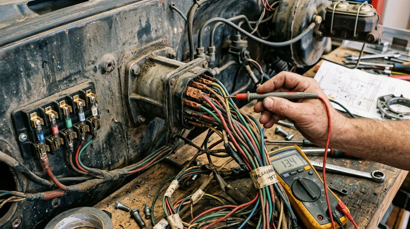
How is the 1973–1987 GM Truck Electrical System Color-Coded?
Factory 1973–1987 GM Squarebody electrical systems utilize a central firewall bulkhead connector dividing engine bay circuits from the interior cab harness. Standard GM color-coding routes 12V constant battery power via red 10 AWG leads, switched ignition via pink leads, starter solenoid engagement via purple leads to terminal S, and ignition coil power via pink wires (or resistance wire on pre-1975 points distributors).
Throughout the 15-year production run of third-generation Chevrolet and GMC C/K trucks, General Motors adhered strictly to a standardized electrical color-coding protocol across both two-wheel-drive master GM truck technical guide platforms like the C10 and four-wheel-drive workhorses like the K10. Understanding these standard color conventions is critical when performing restorations, engine swaps, or modern electronic fuel injection conversions.
The primary trunk of the electrical system is anchored by 10 AWG red un-fused battery leads that branch from the starter solenoid battery terminal to the junction block and firewall bulkhead. These high-amperage feeds are protected at their origin by molded fusible links (typically 14 AWG or 16 AWG wire with non-flammable hypalon insulation) designed to sacrifice themselves in the event of an unfused dead short before harness fires occur.
Interactive Color-Coded Circuit Viewer & Bulkhead Pinout
Firewall Bulkhead & Electrical Pinout Explorer
Inspect factory GM wiring color codes, circuit pathways, fuse ratings, and common failure points across ignition, starting, and lighting harnesses.
12V Constant Battery Power
Direct unswitched battery feed from the starter solenoid lug through two 16-gauge fusible links into the cab bulkhead.
12V Switched Ignition (Run & Start)
Hot in both RUN and START switch positions. Directly supplies primary 12V excitation power to the HEI distributor coil cap.
Starter Solenoid Engagement Circuit
Carries high-current solenoid trigger pulse when key is held in START. Common failure point is mechanical misalignment in column switch.
Accessory Power Circuit
Hot in RUN and ACCESSORY positions, dead during cranking (START) to reserve full battery amperage for starter motor draw.
Tail & Parking Lamp Circuit
Runs through firewall bulkhead to rear chassis harness along driver side frame rail to tail light junction.
Fuel Level Sender Circuit
Operates on standard GM 0–90 Ohm resistance sweep (0 Ohms = Empty, 45 Ohms = 1/2 Tank, 90 Ohms = Full). A disconnected ground registers as past Full.
Brake Stop Lamp & Hazard Circuit
Constant 12V battery power feeds brake pedal switch via orange wire; depressing brake outputs 12V via white wire into steering column turn signal switch.
Ignition Switch, Starter Circuit & HEI Distributor Wiring
The mechanical Ignition Switch on GM Squarebody trucks is mounted on the lower steering column jacket rather than in the dashboard key tumbler, actuated by an internal steel linkage rod. When the key turns to "CRANK", the switch simultaneously supplies 12V down the 12 AWG purple wire to terminal 'S' on the starter solenoid and energizes the ignition feed.
For vehicles equipped with high-energy ignition, the GM Delco HEI distributor requires an uninterrupted, un-ballasted 12.0V switched power source during both "CRANK" and "RUN" modes. Pre-1975 trucks originally equipped with contact breaker points utilized an engineered 1.8-ohm cloth-braided resistance wire routed from the firewall bulkhead. Upgrading a 1973–1974 truck to HEI or installing a modern Holley Sniper EFI system requires discarding this resistance wire completely and running a fresh 12 AWG pink lead directly from the fuse block IGN terminal to ensure battery voltage never drops below the critical 10.5V threshold during cranking.
When setting up ignition timing on traditional Small Block or Big Block Chevrolet V8 platforms, always observe the standard clockwise Firing Order: 1-8-4-3-6-5-7-2, with cylinder #1 located at the front driver side of the engine block.
Dual Fuel Tank Switching Valve Wiring & Fuel Gauge Circuit
Optional auxiliary fuel tanks (RPO NL2) introduced complex pneumatic and electromechanical switching harnesses. 1973 through 1980 trucks utilized a 3-port motorized or vacuum-operated valve, whereas 1981 through 1987 trucks integrated a robust 6-port motorized Pollak switching valve mounted to the inside of the passenger side frame rail.
The dashboard dual-tank selector switch directs voltage to reverse the DC motor polarity inside the 6-port valve, mechanically toggling the fuel supply and vapor return lines between the left and right saddle tanks. Integrated electrical contacts inside the valve simultaneously route the corresponding 0–90 ohm sender signal (tan/white lead) from either the left or right tank to the instrument cluster gauge.
Harness routing along the driver-side frame rail also houses neutral safety switch and reverse backup light circuits wired in tandem with the transmission. Whether your truck features a column-shifted automatic like the TH350, TH400, or 700R4, or a floor-shifted 4-speed manual SM465 or 5-speed NV3500, verify your neutral safety switch linkages and reverse light switches via our transmission electrical neutral safety switch specs. Ensure all chassis harness grounds are securely bonded to bare metal when routing wiring past 10-Bolt, 12-Bolt, and 14-Bolt rear axle assemblies.
Frequently Asked Questions About Squarebody Electrical Problems
01Why does my fuel gauge read past full on a GM Squarebody?
A fuel gauge pegged past full indicates an open circuit (infinite resistance) between the fuel tank sending unit and the gauge cluster. GM fuel senders operate on a 0-90 ohm standard (0 ohms = Empty, 90 ohms = Full). Common causes include a broken pink/tan wire along the frame rail, a disconnected sending unit ground wire attached to the frame crossmember, or a corroded dash cluster printed circuit board connector.
02Can I power an HEI distributor with the original 1973–1974 points wire?
No. Pre-1975 points ignition systems used an intentional 1.8-ohm cloth-covered resistance wire to step down running voltage to 9–10 volts to prevent burning ignition points. An HEI distributor requires a full 12.0+ volts during both cranking and running. Running HEI on resistance wire causes weak spark, ignition misfires at high RPM, and hard hot-start conditions. Replace this circuit with a direct 12 AWG pink wire connected to the fuse panel IGN terminal.
03What causes headlights to flicker or cut out entirely on Squarebody trucks?
Headlight cutout is almost always triggered by the thermal internal circuit breaker inside the factory headlight switch. As halogen headlight conversions pull higher current through aging 40-year-old factory 16 AWG wiring and corroded bulkhead pins, resistance creates excessive heat, tripping the internal thermal breaker. Installing an external dual-relay harness draws high current directly from the battery/alternator post, relieving cab switch load.
04How does the dual fuel tank solenoid valve switch on 1973–1987 trucks?
GM used two primary designs: a 3-port vacuum-assisted or electromagnetic solenoid valve (1973–1980) and a motorized 6-port Pollak-style valve (1981–1987). The dash switch directs 12V power to energize the solenoid or reverse polarity on the motorized valve to toggle fuel supply and return lines while simultaneously toggling the fuel gauge sender lead between the left and right sending units.
Topical Engineering & Calculation Architecture Roadmap
Multi-phase expansion pipeline modeling all statutory, thermodynamic, and mechanical dependencies.
Core Sizing & Foundational Architecture
Primary real-time simulators, dimensional blueprints, and electrical/spatial tolerances.
Advanced Electrical & Sub-System Synthesis
DC-DC charging curves, alternator heat dissipation matrices, and solar MPPT efficiency models.
Environmental & Thermal Dynamics
R-value condensation envelopes, psychrometric heating loads, and passive ventilation airflow models.
Plumbing, Fluid Mechanics & Greywater Loops
PEX piping friction loss calculations, 12V diaphragm pump pressure drops, and freeze-risk mitigation.
Chassis Weight Distribution & Axle Equilibrium
Center of gravity (CoG) 3D coordinate modeling, GVWR compliance, and suspension deflection ratios.